Introduction:
In this tutorial, we will learn how to create a Light Sensor Circuit Using LDR and 555 Timer with Adjustable sensitivity, and a few other electronic components. This circuit detects the intensity of light incident on the LDR and activates an LED when the light reaches a certain level. The LED can be replaced with other electronic devices such as buzzers, relays, or DC motors. We will explore the working of this circuit and discover other interesting applications.
Hardware Required:
| 1 | × | 555 Timer IC |
| 1 | × | Light Dependant Resistor (LDR) |
| 1 | x | 100K Potentiometer |
| – | × | Resistors: 2 x 10K, 330R |
| – | × | Light Emitting Diode (LED) |
| 1 | x | Few Breadboard Connectors |
| 1 | x | Breadboard |
| 1 | x | (5-12)V Power Supply |
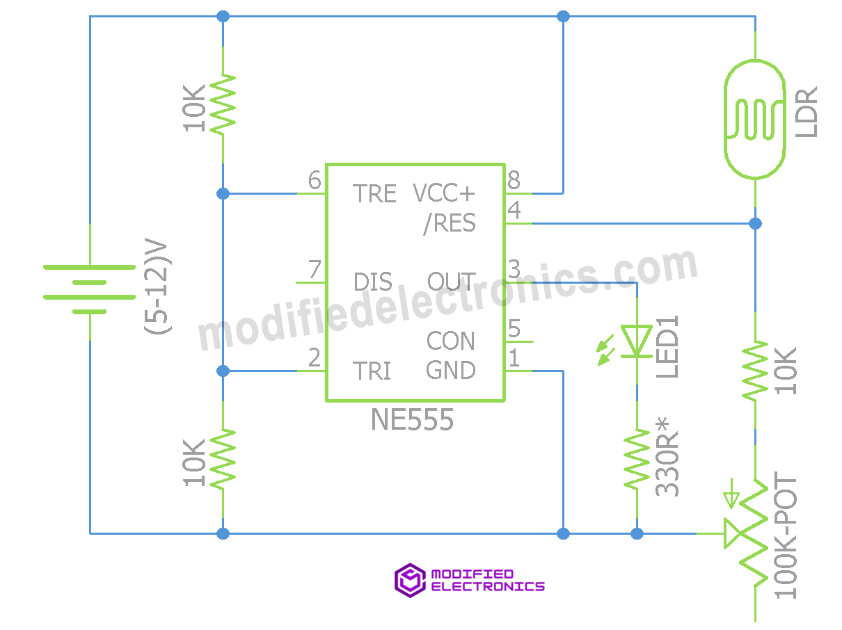
Circuit Diagram:
Instructions to Build This Circuit:
- Place the 555 Timer IC on the Breadboard: Orient the IC so that its notch faces left, and pin-numbering starts from the bottom left.
- Connect Power Supply to IC Pins: Attach Pin-8 to the positive rail and Pin-1 to the negative rail on the breadboard.
- Connect Pins 2 and 6: These pins need to be connected together.
- Install 10K Resistors: Connect one terminal of a 10K resistor to Pin-2 and another terminal to the negative rail. Repeat this step for Pin-6.
- Incorporate the LDR: Connect one terminal of the LDR to Pin-4 of the 555 timer IC and the other terminal to the positive rail.
- Add a 4.7K Resistor: Connect one terminal to Pin-4 of the IC.
- Integrate a 100K Potentiometer: Connect one end to the other terminal of the 4.7K resistor, and the center terminal to the negative rail.
- Connect the LED: Place the LED on the breadboard with its anode connected to Pin-3 of the IC. Insert a 330R resistor between the cathode of the LED and the negative rail.
- Connect Power Supply: Now, connect the power supply to the circuit.
How This Circuit Works:
The operation of this circuit hinges on the behavior of the LDR, which exhibits resistance inversely proportional to the intensity of incident light. When light intensity is high, LDR resistance diminishes, and vice versa.
Simultaneously, the 555 timer IC activates when its reset pin (Pin-4) registers a voltage above 0.8V. If the voltage at Pins 2 and 6 falls between 1/3rd and 2/3rd of the supply voltage, the output turns on.
By creating a voltage divider with the LDR and a resistor/potentiometer combination, connected to Pin-4 of the 555 timer IC, we control its activation. In darkness, the voltage at the voltage divider drops below 0.8V, deactivating the IC. Conversely, sufficient light raises the voltage, activating the IC.
Applications
- Automatic Street Light Circuits: Employed for efficient energy usage by automatically activating street lights based on ambient light levels.
- Wardrobe or Locker Lights: Automatically turn on interior lights when the space is accessed, enhancing convenience and visibility.
- Burglar Alarm Systems: Utilized in security systems that respond to visible light changes, such as detecting unauthorized entry or movement.