Introduction
In this blog post, we will explore the concept of an Automatic Garden Light Circuit Using LDR & FIR3D SCR. This circuit is designed to automatically turn on and off the garden lights based on the ambient light conditions. It is a simple and efficient solution to ensure that your garden lights are only active when needed, saving energy and extending the lifespan of the lights.
Hardware Required
| 1 | × | FIR3D SCR |
| 4 | × | 1N4007 Diodes |
| 1 | × | Resistor (1MΩ) |
| 1 | × | Light Dependent Resistor (LDR) |
| 1 | × | Lamp (bulb or LED bulb) |
| 1 | x | 220V AC input |
| 1 | × | Switch |
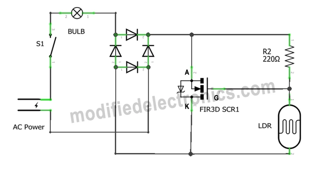
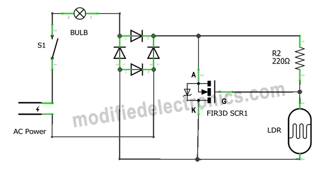
Circuit Diagram

Working Principle
The Automatic Garden Light Circuit Using LDR & FIR3D SCR operates based on the principle of the LDR’s light sensing capabilities. The LDR is a variable resistor that changes its resistance based on the intensity of light falling on it. When the ambient light is low (such as during the evening or night), the resistance of the LDR increases, triggering the transistor to turn on the relay. This, in turn, powers the garden lights.
On the other hand, when the ambient light is high (such as during the day), the resistance of the LDR decreases, causing the transistor to turn off the relay. Consequently, the garden lights are switched off to conserve energy.
Implementation
To implement this circuit, follow these steps:
- Connect the LDR in series with a 10k Ohm resistor.
- Connect the junction of the LDR and the resistor to the base of the NPN transistor.
- Connect the emitter of the transistor to the ground.
- Connect the collector of the transistor to the positive terminal of the relay.
- Connect the negative terminal of the relay to the ground.
- Connect the positive terminal of the battery to the common terminal of the relay.
- Connect the normally open (NO) terminal of the relay to the positive terminal of the LED.
- Connect the negative terminal of the LED to the ground.
- Connect a diode (1N4007) across the relay coil to protect the transistor from back EMF.
- Connect a 1000uF capacitor across the relay coil to prevent voltage spikes.
Conclusion
By building an automatic garden light circuit using an LDR, you can ensure that your garden lights are only active when needed. This not only saves energy but also extends the lifespan of the lights. With a few simple components and the circuit diagram provided, you can easily implement this circuit and enjoy the convenience and efficiency it offers.
