Introduction
Creating a Traffic Light Project using Arduino is a fun and educational way to delve into electronics and programming. It allows you to simulate a familiar scenario – traffic lights at an intersection – while learning the basics of control systems and coding. In this project, we’ll explore How to Make Traffic Light Project using Arduino and a Traffic Light Module.
Hardware Required
What is a Traffic Light Project?
A Traffic Light Project using Arduino involves emulating the behavior of a standard traffic signal. It consists of three lights: red, yellow, and green, each with its specific timing sequence. These lights change in a way that mimics real traffic lights, controlling the flow of “traffic” in your miniature world.
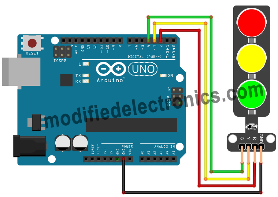
Circuit Diagram
Code
#define PIN_RED    2 // The Arduino pin connected to R pin of traffic light module
#define PIN_YELLOW 3 // The Arduino pin connected to Y pin of traffic light module
#define PIN_GREEN  4 // The Arduino pin connected to G pin of traffic light module

#define RED_TIME     4000 // RED time in millisecond
#define YELLOW_TIME  4000 // YELLOW time in millisecond
#define GREEN_TIME   4000 // GREEN time in millisecond

void setup() {
  pinMode(PIN_RED, OUTPUT);
  pinMode(PIN_YELLOW, OUTPUT);
  pinMode(PIN_GREEN, OUTPUT);
}

// the loop function runs over and over again forever
void loop() {
  // red light on
  digitalWrite(PIN_RED, HIGH);   // turn on
  digitalWrite(PIN_YELLOW, LOW); // turn off
  digitalWrite(PIN_GREEN, LOW);  // turn off
  delay(RED_TIME); // keep red light on during a period of time

  // yellow light on
  digitalWrite(PIN_RED, LOW);    // turn off
  digitalWrite(PIN_YELLOW, HIGH); // turn on
  digitalWrite(PIN_GREEN, LOW); // turn off
  delay(YELLOW_TIME); // keep yellow light on during a period of time

  // green light on
  digitalWrite(PIN_RED, LOW);    // turn off
  digitalWrite(PIN_YELLOW, LOW); // turn off
  digitalWrite(PIN_GREEN, HIGH); // turn on
  delay(GREEN_TIME); // keep green light on during a period of time
}
Code Work
The provided code defines the pins to which the Traffic Light Module’s red, yellow, and green LEDs are connected. It specifies the timing for each light, emulating a standard traffic light sequence – red, yellow, and green. Here’s a breakdown of the code:
- Setup: The setup function initializes the pins connected to the LEDs as OUTPUT.
- Loop: In the loop function, the code cycles through the traffic light sequence:
- The red LED turns on for a specified duration (RED_TIME).
- Next, the yellow LED is activated for a set duration (YELLOW_TIME).
- Finally, the green LED is illuminated for a specified time (GREEN_TIME).
By repeating this loop, you create a continuous traffic light sequence, simulating the operation of a real traffic light.
Application of the Traffic Light Project
- Educational Tool: Ideal for teaching basic electronics and programming concepts.
- Traffic Simulation: Use in model city displays, school projects, or driving simulations.
- Safety Awareness: Promote road safety by demonstrating the importance of traffic lights.
- Interactive Displays: Incorporate into interactive art installations and exhibitions.
- Prototype Testing: Test traffic management algorithms for real-world applications.