Introduction
The Push Button and LED | Arduino Tutorial introduces an essential aspect of electronics and microcontroller programming. This project demonstrates how to use a simple push button to control the state of an LED. With an Arduino UNO and a handful of basic components, you’ll explore the fundamental concept of digital input and output, providing a foundation for more complex projects.
Hardware Required
What is the “Push Button and LED” Tutorial?
The Push Button and LED | Arduino Tutorial is a practical introduction to two essential electronic components and their interaction with an Arduino. A push button serves as the input device, allowing users to control the LED’s state. The LED, on the other hand, is the output, providing a visual indicator of the button’s status. This project lays the foundation for understanding digital input and output in Arduino programming.
How It Works
The operation of the Push Button and LED | Arduino Tutorial is straightforward. When the push button is pressed, it creates an electrical connection between its two terminals. This connection is detected by the Arduino, which reads the button’s state as LOW. When the button is not pressed, the Arduino reads the state as HIGH.
The Arduino uses this information to control the LED. When the button is pressed (LOW state), the Arduino turns on the LED. When the button is not pressed (HIGH state), the Arduino turns off the LED. This simple interaction demonstrates how digital inputs and outputs work in Arduino.
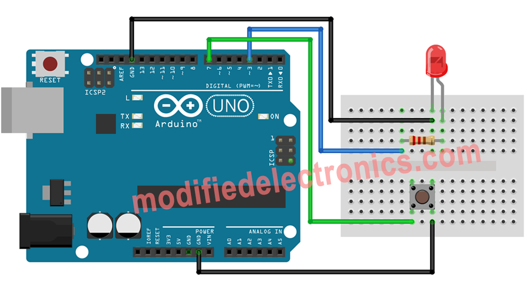
Circuit Diagram

How to Program
Programming the Push Button and LED | Arduino Tutorial involves reading the state of the push button and controlling the LED accordingly. The code provided defines the pin numbers for the button and the LED, initializes them, and continuously monitors the button’s state. When the button is pressed, the LED is turned on, and when it’s released, the LED turns off.
Code
// constants won't change. They're used here to set pin numbers:
const int BUTTON_PIN = 7;  // the number of the pushbutton pin
const int LED_PIN =  3;   // the number of the LED pin

// variables will change:
int buttonState = 0;   // variable for reading the pushbutton status

void setup() {
  // initialize the LED pin as an output:
  pinMode(LED_PIN, OUTPUT);
  // initialize the pushbutton pin as an pull-up input:
  // the pull-up input pin will be HIGH when the switch is open and LOW when the switch is closed.
  pinMode(BUTTON_PIN, INPUT_PULLUP);
}

void loop() {
  // read the state of the pushbutton value:
  buttonState = digitalRead(BUTTON_PIN);

  // control LED according to the state of button
  if(buttonState == LOW)         // If button is pressing
    digitalWrite(LED_PIN, HIGH); // turn on LED
  else                           // otherwise, button is not pressing
    digitalWrite(LED_PIN, LOW);  // turn off LED
}
Code Explanation
The code is structured to read the state of the push button and control the LED based on the button’s state. It begins by defining the pin numbers for the button and LED as constants. The setup function initializes the LED pin as an output and the push button pin as an input with a pull-up resistor. The loop function continuously reads the state of the push button, and if it’s pressed (LOW state), it turns on the LED. When the button is released (HIGH state), the LED is turned off.
Application
This simple yet educational project can be applied in various scenarios, including:
- Education: Ideal for teaching the basics of digital input and output to beginners.
- User Interfaces: Learn how to incorporate buttons for user interaction in your projects.
- Prototyping: Use push buttons to trigger actions in your prototypes.
- Custom Control: Integrate buttons and LEDs to create custom control systems.
- Automation: Develop automation solutions that respond to user inputs.